VTK는 Visualization Tookit의 약자로 객체지향기법으로 설계/구현된 3차원 그래픽 라이브러리로 소스가 공개되는 프리웨어입니다. VTK는 C++ 클래스 라이브러리이며, Tcl/Tk, Java, Python과 같은 스크립트 언어에 대한 인터페이스를 함께 제공합니다. VTK는 스칼라, 벡터, 텐서, 텍스쳐, volumetric method 등의 visualization 알고리즘을 지원하고, implicit modeling, polygon reduction, mesh smoothing, cutting, contouring, Delaunay triangulation 등과 같은 고급 모델링 테크닉을 지원합니다. 또한 많은 imaging algorithm을 통합하여 3D graphics algorithm과 데이터를 2D imaging로 믹싱 할 수 있습니다. VTK는 객체지향기법으로 설계 및 구현되어 있습니다. VTK는 거의 모든 Unix 플랫폼과 PC(Windows 98/ME/NT/2000/XP), 그리고 Mac OSX Jaguar 이후 버전에서 사용 가능하고, 철저하게 테스팅되어 있습니다. 이번 강좌는 Windows 전용 VTK 패키지를 빌드하는 방법에 대해 알아봅니다.
요구사항 (Requirements)
PC에 다음의 프로그램이 설치 되어 있어야 합니다.
Visual Studio 2005
ActiveTcl
이 글을 쓰기 위해 사용된 ActiveTcl 버전은 8.4.18입니다.
CMake
이 글을 쓰기 위해 사용된 CMake 버전은 2.4.8입니다.
- http://www.cmake.org/files/v2.4/cmake-2.4.8-win32-x86.exe
다운로드 (Download)
VTK 공식 사이트에서 소스 및 데이터 파일을 다운로드하여 압축을 풉니다.
- http://www.vtk.org/files/release/5.0/vtk-5.0.4.zip
- http://www.vtk.org/files/release/5.0/vtkdata-5.0.4.zip
설치 (Installation)
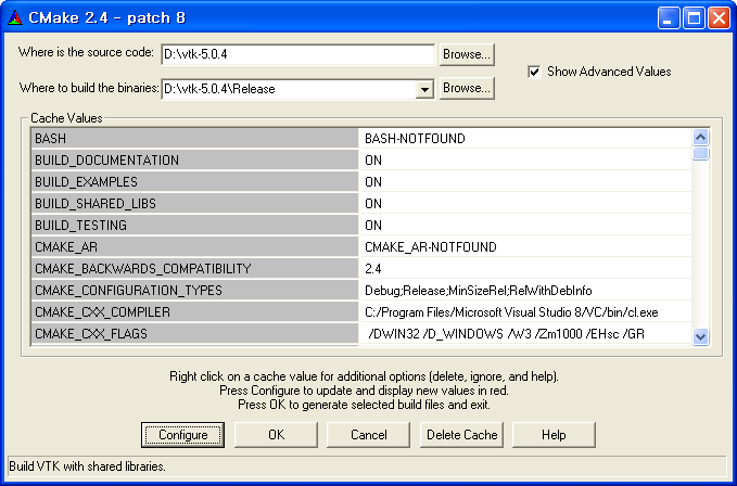
CMake를 실행합니다.

위의 그림과 같이 같이 셋팅한후 Configure 버튼을 누릅니다. Where is the source code 에는 VTK 소스코드 위치를 지정합니다. Where to build the binaries 에는 릴리즈 될 디렉토리 위치를 지정합니다. 다음 아래의 그림과 같이 같이 컴파일러를 선택한 후 OK 버튼을 누릅니다.

지정된 릴리즈 디렉토리가 없으므로 생성할지 물어봅니다. Yes 버튼을 누르면, 빌드를 하기 위한 시스템 정보를 얻는 과정을 거칩니다. 다음 위의 과정이 끝나면 빌드를 하기 옵션을 세팅해야 합니다. 아래의 그림과 같이 세팅을 한 후 Configure 버튼을 한번 더 누릅니다.
다음 Tcl에서 사용하기 위한 [VTK 확장 패키지]를 빌드하기 위한 정보를 세팅합니다. 아래의 그림과 같이 세팅할 부분은 붉은색 부분으로, 기본적인 세팅이 완료되어 있으므로, 확인하고 Configure 버튼을 한 번 더 누릅니다.

아래의 그림과 같이 OK 버튼이 활성화될 것입니다. OK버튼을 눌러 Visual Studio 2005용 프로젝트 파일을 생성합니다.
다음 프로젝트 파일이 정상적으로 생성되면, CMake 프로그램이 자동 종료됩니다. Where to build the binaries로 지정한 디렉토리로 이동한 후 ALL_BUILD.vcproj 파일을 더블클릭하여 Visual Studio 2005를 실행합니다.
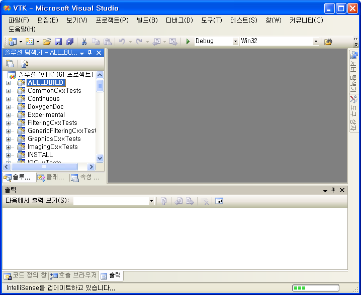
빌드 -> [솔루션 빌드] 를 실행합니다. 오랜 시간이 소모될 것입니다. Where to build the binaries로 지정한 디렉토리내의 Wrapping\Tcl 디렉토리로 이동하여 INSTALL.vcproj 파일을 더블클릭하여 Visual Studio 2005를 실행합니다. 빌드 -> [솔루션 빌드] 를 실행합니다. C:\Program Files\VTK 디렉토리가 생성되며, 기본적인 파일들이 생성됩니다.
VTK 패키지 구성
이제부터 본격적인 VTK 패키지 디렉토리를 구성합니다.(지금부터는 수작업입니다.) 다음 C:\Program Files\VTK 내의 모든 파일들과 디렉토리들을 설치된 ActiveTCL의 디렉토리(C:\Tcl) 로 복사합니다. 다음 Where to build the binaries로 지정한 디렉토리내의 bin\debug 디렉토리로 이동합니다. 아래의 그림과 같은 확장자 *.dll 인 파일들을 ActiveTCL의 bin 디렉토리로 복사합니다.

마지막으로 아래의 그림과 같이 wish를 실행하여 VTK 패키지를 요청해 봅니다. 아래의 그림과 같이 5.0이 리턴된다면 Tcl에서 VTK를 사용하기 위한 빌드과정은 끝입니다. 이제 VTK의 세계로 빠져보길 바랍니다.

옵션 사항
옵션 사항입니다. VTK에서 제공하는 기본적인 예제를 돌려 보기 위해서는 처음 받았던 VTK 데이터 파일들을 ActiveTCL이 설치된 곳의 적당한 곳에 복사합니다. (예: C:\Tcl\lib\vtk-5.0\Data) 다음 환경변수 VTK_DATA_ROOT를 아래의 그림과 같이 생성합니다.

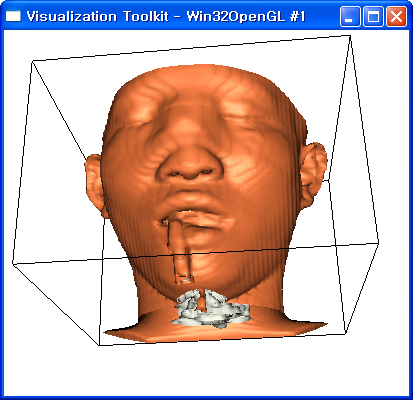
다음 VTK에서 제공하는 예제인 Examples 디렉토리를 ActiveTCL이 설치된 곳의 적당한 곳에 복사합니다. (예: C:\Tcl\lib\vtk-5.0\Examples) 다음 적당한 예제를 돌려봅니다. 예로 C:\Tcl\lib\vtk-5.0\Examples\Medical\Tcl\Medical2.tcl를 더블클릭하여 예제를 실행해 봅니다. 아래의 그림 같은 화면을 볼 수 있을 것입니다.
package require vtk
package require vtkinteraction

#
# This example reads a volume dataset, extracts two isosurfaces that
# represent the skin and bone, and then displays them.
#

# Create the renderer, the render window, and the interactor. The renderer
# draws into the render window, the interactor enables mouse- and
# keyboard-based interaction with the scene.
#
vtkRenderer aRenderer
vtkRenderWindow renWin
  renWin AddRenderer aRenderer
vtkRenderWindowInteractor iren
  iren SetRenderWindow renWin

# The following reader is used to read a series of 2D slices (images)
# that compose the volume. The slice dimensions are set, and the
# pixel spacing. The data Endianness must also be specified. The reader
# usese the FilePrefix in combination with the slice number to construct
# filenames using the format FilePrefix.%d. (In this case the FilePrefix
# is the root name of the file: quarter.)
vtkVolume16Reader v16
  v16 SetDataDimensions 64 64
  v16 SetDataByteOrderToLittleEndian
  v16 SetFilePrefix  "$VTK_DATA_ROOT/Data/headsq/quarter"
  v16 SetImageRange 1 93
  v16 SetDataSpacing  3.2 3.2 1.5

# An isosurface, or contour value of 500 is known to correspond to the
# skin of the patient. Once generated, a vtkPolyDataNormals filter is
# is used to create normals for smooth surface shading during rendering.
# The triangle stripper is used to create triangle strips from the
# isosurface these render much faster on may systems.
vtkContourFilter skinExtractor
  skinExtractor SetInputConnection [v16 GetOutputPort]
  skinExtractor SetValue 0 500
vtkPolyDataNormals skinNormals
  skinNormals SetInputConnection [skinExtractor GetOutputPort]
  skinNormals SetFeatureAngle 60.0
vtkStripper skinStripper
  skinStripper SetInputConnection [skinNormals GetOutputPort]
vtkPolyDataMapper skinMapper
  skinMapper SetInputConnection [skinStripper GetOutputPort]
  skinMapper ScalarVisibilityOff
vtkActor skin
  skin SetMapper skinMapper
  [skin GetProperty]  SetDiffuseColor 1 .49 .25
  [skin GetProperty] SetSpecular .3
  [skin GetProperty] SetSpecularPower 20

# An isosurface, or contour value of 1150 is known to correspond to the
# skin of the patient. Once generated, a vtkPolyDataNormals filter is
# is used to create normals for smooth surface shading during rendering.
# The triangle stripper is used to create triangle strips from the
# isosurface these render much faster on may systems.
vtkContourFilter boneExtractor
  boneExtractor SetInputConnection [v16 GetOutputPort]
  boneExtractor SetValue 0 1150
vtkPolyDataNormals boneNormals
  boneNormals SetInputConnection [boneExtractor GetOutputPort]
  boneNormals SetFeatureAngle 60.0
vtkStripper boneStripper
  boneStripper SetInputConnection [boneNormals GetOutputPort]
vtkPolyDataMapper boneMapper
  boneMapper SetInputConnection [boneStripper GetOutputPort]
  boneMapper ScalarVisibilityOff
vtkActor bone
  bone SetMapper boneMapper
  [bone GetProperty] SetDiffuseColor 1 1 .9412

# An outline provides context around the data.
#
vtkOutlineFilter outlineData
  outlineData SetInputConnection [v16 GetOutputPort]
vtkPolyDataMapper mapOutline
  mapOutline SetInputConnection [outlineData GetOutputPort]
vtkActor outline
  outline SetMapper mapOutline
  [outline GetProperty] SetColor 0 0 0

# It is convenient to create an initial view of the data. The FocalPoint
# and Position form a vector direction. Later on (ResetCamera() method)
# this vector is used to position the camera to look at the data in
# this direction.
vtkCamera aCamera
  aCamera SetViewUp  0 0 -1
  aCamera SetPosition  0 1 0
  aCamera SetFocalPoint  0 0 0
  aCamera ComputeViewPlaneNormal

# Actors are added to the renderer. An initial camera view is created.
# The Dolly() method moves the camera towards the FocalPoint,
# thereby enlarging the image.
aRenderer AddActor outline
aRenderer AddActor skin
aRenderer AddActor bone
aRenderer SetActiveCamera aCamera
aRenderer ResetCamera
aCamera Dolly 1.5

# Set a background color for the renderer and set the size of the
# render window (expressed in pixels).
aRenderer SetBackground 1 1 1
renWin SetSize 640 480

# Note that when camera movement occurs (as it does in the Dolly()
# method), the clipping planes often need adjusting. Clipping planes
# consist of two planes: near and far along the view direction. The
# near plane clips out objects in front of the plane the far plane
# clips out objects behind the plane. This way only what is drawn
# between the planes is actually rendered.
aRenderer ResetCameraClippingRange

# Set up a callback (using command/observer) to bring up the Tcl
# command GUI when the keypress-u (UserEvent) key is pressed.
iren AddObserver UserEvent {wm deiconify .vtkInteract}

# Interact with data. The Tcl/Tk event loop is started automatically.
iren Initialize
wm withdraw .
최종적인 디렉토리 구조와 파일은 첨부파일 result.txt와 같습니다.
금, 01/09/2009 - 16:15 — zaskateam
배포판으로 빌드 하시려면 아래와 같이 해 주시면 편리합니다.
빌드 -> 구성 관리자 -> Debug를 Release 바꾸신 후 [솔루션 빌드]를 하세요.
다음 Where to build the binaries로 지정한 디렉토리내의 bin\release 디렉토리에 있는 dll 파일들을 복사해 갑니다.
Visual studio 2005에서는 6.0과는 달리 debug와 release가 모드가 있어서,
배포판으로 빌드 하시려면 release로 하시는 것이 좋습니다.
Debug로 하셨다면 배포하신 컴퓨터에서도 debuger가 설치되어 있거나
추가로 몇 개의 dll 파일들을 복사해 주셔야 합니다.
참고하세요~